Beyond the Interface: The Ultimate Guide to UDF CFD Simulation in ANSYS Fluent
Engineering is rarely simple. In the real world, winds do not blow at a constant speed, materials do not always behave normally, and machines move in complex ways. When engineers use simulation software to solve these problems, they often hit a wall. Standard software is great for standard problems, but it cannot do everything.
Most engineers use ANSYS Fluent for their simulations. It is a powerful tool with many buttons and menus. However, there comes a time when the menu does not have the option you need. Maybe you need a temperature that changes every second, or a chemical reaction that follows a unique rule. When the standard options are not enough, you need a custom solution.
This is where the power of a UDF CFD Simulation comes in. UDF stands for User-Defined Function. It is the key that unlocks the full potential of the software. Instead of just clicking buttons, you become the creator. You write a small computer program that tells the software exactly what to do.
At CFDLAND, we encounter these complex challenges every day. We specialize in using these custom functions to solve problems that seem impossible. In this complete guide, we will explore what UDFs are, how they work, and how you can use them to master your simulations. We will write this in simple terms so you can understand the logic behind the code.

Figure 1: From moving parts to custom heat profiles, UDFs allow for limitless customization in CFD.
What is a User-Defined Function (UDF)?
To understand a UDF, you must first understand how ANSYS Fluent works. Imagine the software is a calculator. Usually, you type in numbers, and it gives you an answer. But what if you want the calculator to do a math operation that hasn’t been invented yet?
A User-Defined Function (UDF) is a routine written in the C programming language. It acts as a bridge between you and the Fluent solver. The solver is the engine that does the math. The UDF allows you to change how that engine works while it is running.
You can use a UDF to:
- Customize boundary conditions (like a wind profile).
- Define new material properties (like a fluid that gets thicker when moved).
- Add source terms (like heat generated by a chemical reaction).
- Control mesh motion (moving parts).
- Initialize a solution with a specific data field.
The Language: C for CFD
You do not need to be a professional software developer to write a UDF, but you need to know the basics of C. The code uses special commands called DEFINE macros. Think of a “Macro” as a shortcut. ANSYS Fluent has already written the hard code for you. You just use the macro to tell it where to apply your logic. For example, DEFINE_PROFILE is used to set values at a boundary, while DEFINE_PROPERTY is used to change material density or viscosity.
Three Pillars: UDF, UDM, and UDS
When working on advanced CFD customization, you will often hear three acronyms: UDF, UDM, and UDS. They work together to solve complex problems. Let’s break them down simply.
1. User-Defined Functions (UDF)
As we discussed, this is the “Brain.” It is the code that contains the logic and the equations. It tells the simulation what to do.
2. User-Defined Memory (UDM)
Sometimes, your code needs to remember things. Imagine you are simulating a pipe that gets dirty over time. You need to know how much dirt was there one second ago to calculate how much dirt is there now. Standard Fluent variables (like Pressure or Velocity) cannot store this “dirt” value.
User-Defined Memory (UDM) solves this. It gives you blank memory slots in every single cell of your mesh.
- Think of the mesh as a grid of thousands of small boxes.
- UDM puts a small “sticky note” in every box.
- Your UDF can write a number on that note and read it later.
- This is essential for time-dependent simulations or complex history tracking.
3. User-Defined Scalars (UDS)
A scalar is just a fancy word for a value, like temperature or concentration. Standard Fluent solves equations for standard scalars (Pressure, Temperature, Turbulence). But what if you want to track something weird? For example, the “age” of the air inside a room, or the concentration of a specific electric charge.
User-Defined Scalars (UDS) allow you to create your own transport equation.
- UDM just stores data (it sits still).
- UDS moves data (it flows with the wind).
- Fluent calculates how your custom scalar flows, spreads, and reacts using the flow field.
Interpreted vs. Compiled: Which to Choose?
When you write your C code, you have two ways to put it into ANSYS Fluent. This is often a confusing choice for beginners.
Interpreted UDFs
This is the “Quick and Easy” method.
- How it works: Fluent reads your text file line-by-line while the simulation runs.
- Pros: It is very easy to set up. You don’t need to install a separate compiler. It is great for simple math or quick tests.
- Cons: It is slow. Because the computer reads the code every time, it slows down the simulation. It also cannot use some advanced C features.
Compiled UDFs
This is the “Professional” method.
- How it works: You use a C compiler (like Visual Studio) to translate your text code into machine language (a shared library) before the simulation starts.
- Pros: It is very fast. It runs at the same speed as the internal Fluent code. It is necessary for complex arrays, large simulations, and using UDM/UDS.
- Cons: It takes a bit of time to set up the compiler on your computer.
At CFDLAND, we almost always use Compiled UDFs because they offer better stability and speed for our clients’ projects.
Real-World Applications
Theory is good, but examples are better. Let’s look at how we use UDF CFD Simulation to solve real engineering problems. These are based on actual challenges.
Custom Boundary Conditions: The Solar Collector
In a standard simulation, you might say “The wall temperature is 300 Kelvin.” But in reality, nature is not constant. Consider a Parabolic Trough Collector. This is a solar energy device. The sun shines on a tube to heat the oil inside. However, the sun only hits the bottom of the tube. The top is in the shadow.
- Standard Fluent: Can only set a constant temperature for the whole tube. This is wrong.
- With UDF: We use the DEFINE_PROFILE macro. We write a math formula that checks the position (x, y, z) of each face on the tube. If the face points down, it gets high heat (Sun). If it points up, it gets low heat (Shadow).
- Result: A highly accurate simulation that matches real experimental data.

Figure 2: Using UDFs to apply realistic, non-uniform heat distribution on a solar receiver.
Advanced Material Properties: Changing Conductivity
Materials are not always simple. In a Heterogeneous Thermal Conductivity project, we had to model a composite wall. The material was not the same everywhere. It was a mix of metal and plastic, meaning the ability to conduct heat changed every millimeter.
- With UDF: We used the DEFINE_PROPERTY macro. The code looked at the coordinate of the cell. Based on the location, it calculated the exact conductivity for that specific spot.
- Result: We could see exactly how heat flowed through the complex composite material.

Figure 3: A contour plot showing how material properties change based on location, defined by code.
Dynamic Mesh: Moving Machines
This is one of the most exciting applications. Many machines move: pumps spin, valves open, and wings flutter. Standard CFD is good for static (still) objects. But for moving parts, we need a Dynamic Mesh CFD Simulation. We worked on a project involving Oscillating Cylinders underwater. The water flow made the cylinders vibrate.
- With UDF: We used the DEFINE_CG_MOTION macro. This tells the software the speed and direction of the object. We programmed the cylinder to move back and forth using a sine wave equation.
- Result: We could capture the complex Fluid-Structure Interaction (FSI). The mesh moved and stretched automatically as the cylinder vibrated.

Figure 4: A UDF controls the movement of the cylinders, allowing the mesh to deform and adapt in real-time.
Chemical Reactions: The UV Reactor
In water treatment, UV light is used to clean water. We simulated a UV/H2O2 Reactor. The cleaning power depends on how much UV light hits the water.
- Step 1 (UDS): We used a User-Defined Scalar to simulate the UV light intensity spreading through the water.
- Step 2 (UDF): We used a DEFINE_SOURCE macro. This macro told the software: “If UV light is high here, destroy the pollution faster.”
- Result: We could predict exactly how clean the water would be at the outlet.

Figure 5: Complex chemistry modeling where the reaction rate is controlled by a custom UDF script.
How to Write and Compile a UDF
If you want to try this yourself, here is the basic workflow. It can be tricky at first, so follow these steps carefully.
Step 1: Write the Code
Open a simple text editor (like Notepad++). Do not use Word. You will write your C code here. A basic structure looks like this:
- Include the Header: #include "udf.h" (This tells the code to use Fluent’s library).
- Define the Macro: DEFINE_PROFILE(name, thread, position)
- Loop over Faces: You write a loop that visits every face on the boundary.
- Apply the Equation: F_PROFILE(face, thread) = ... (Your math goes here). Save the file with a .c extension, for example, my_code.c.
Step 2: Prepare the Compiler
If you are on Windows, you usually need Microsoft Visual Studio. You must ensure that the “Environment Variables” are set correctly so that Fluent can find the compiler. This is often the hardest part for beginners.
Step 3: Build in Fluent
- Open ANSYS Fluent.
- Go to the User-Defined tab.
- Select Functions -> Compiled.
- Click Add and select your my_code.c file.
- Click Build. Watch the console window. If you see “Done,” it worked. If you see “Error,” you have a syntax mistake in your code.
- Click Load.
Step 4: Hook the Function
Just loading the code is not enough. You must tell Fluent where to use it.
- Open the Boundary Conditions panel.
- Select your inlet or wall.
- Next to “Temperature” or “Velocity,” click the dropdown menu.
- Instead of “Constant,” select “udf my_code”.
Now, when you run the simulation, Fluent will ask your code for the value at every single time step.
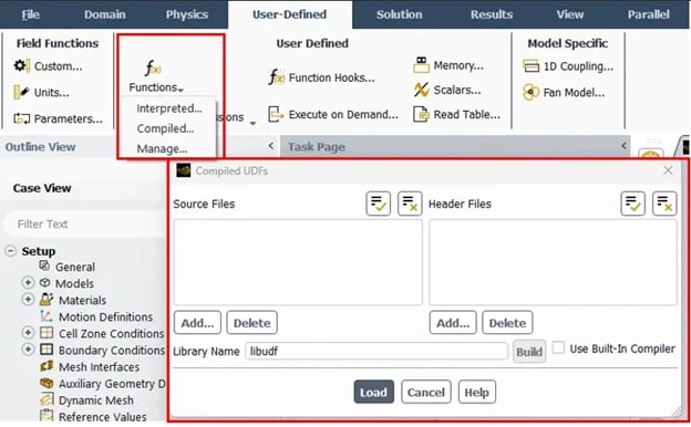
Figure 6: The compilation interface. Seeing “Done” here is the goal of every CFD engineer.
Common Challenges and Debugging
Writing UDFs is not always smooth. Here are common problems you might face.
Syntax Errors
The C language is very strict. If you miss a semi-colon ; at the end of a line, the code will not build. If you forget a bracket }, it will fail.
- Tip: Read the error message in the console. It usually tells you exactly which line number has the problem.
Segmentation Faults
This is the most famous error. It means your code tried to access memory that doesn’t exist.
- Example: You tried to access UDM (memory) but you forgot to increase the number of memory locations in the Fluent GUI settings.
- Fix: Always check your setup. If your code uses 2 memory slots, make sure you set “Number of UDM” to 2 in the interface.
Parallel Issues
Modern computers use multiple cores (Parallel processing). Fluent splits the mesh into pieces.
- The Problem: Sometimes your UDF runs on the “Host” (the manager) but tries to access data on the “Node” (the worker). This causes a crash.
- The Fix: You need to use special compiler directives like #if !RP_HOST to make sure the right code runs on the right processor.
Conclusion: Unlock Your CFD Potential with CFDLAND
User-Defined Functions (UDFs) are the secret weapon of the CFD expert. They allow you to break the rules of standard software and simulate the real world with incredible accuracy. From the dynamic mesh of a beating heart to the complex combustion of a rocket engine, UDFs make it possible.
However, we understand that learning C programming and debugging compilation errors can be frustrating. It takes time to master the syntax, the macros, and the logic.
At CFDLAND, we have spent years mastering these tools. We specialize in creating custom UDF CFD Simulation solutions for clients worldwide. Whether you need a simple boundary profile or a complex multi-physics model, our team can write the code, debug the errors, and deliver the results you need.
Do not let the limitations of the standard menu stop your engineering progress. Embrace the power of customization. If you are stuck, or if you have a project that requires advanced modeling, we are here to help. Explore our tutorials, download our examples, and let us help you turn your most difficult simulation challenges into successful engineering solutions.
Comments
Loading comments…